GLSL #10: RGB-D画像からの頂点・法線マップ生成
目標
前回(下記参照)は,Compute Shaderを使って,3DCGを描画した際に生成されるZバッファの線形化を行うプログラムを作成した.今回は,RGB-D画像を用いて,頂点・法線マップを生成するプログラムを作成する.尚,RGB-D画像は,Zバッファの様に非線形化は行われていないため,線形化する必要はありません.
実装環境
- Windows 10 64bit
- Visual Studio 2015
- GLEW 3.2.1
- 設定方法はこちらを参照
- GLEW 1.13.0
- 設定方法はこちらを参照
- GLM
- 設定方法はこちらを参照
- DevIL
- 設定方法はこちらを参照
- OpenCV
- 設定方法は外部のWebサイトを参照
- 尚,contribは必要なし
処理内容
流れ
- RGB-D画像読み込み
- TUM RGB-D Dataset等から適当なものをダウンロードしておく
- もしくは,自らKinectやXtionから取得しておく/実時間で取得する
- Compute Shaderを使って頂点マップを生成
- 頂点マップとは,RGB-D画像の各画素に対応するfloat型3チャンネルの画像
- Compute Shaderを使って法線マップを生成
- 法線マップとは,RGB-D画像の各画素に対応するfloat型3チャンネルの画像
- 生成した頂点・法線マップを描画
頂点マップの計算
参考文献1の3章によると,以下の式によって,フレーム目の奥行マップ
から
フレーム目の頂点マップ
が生成できる.
この時,は画像上の2次元位置,
は求めたい頂点マップ
の
に対応する頂点,
は
に対応する奥行値,
は事前の校正により既知である内部パラメータ行列を表す.
「」の部分は,出力される
が実数の3次元ベクトルであることを表しているだけである.尚,ここでは,1フレーム(1枚の画像)のみ入力することを考えて,
は無視する.以上より,シェーダで記述する式は以下のようになる.
法線マップの計算
ここでも参考文献1の3章に倣って,Central Differenceを取ることで,頂点マップから法線マップ
を計算する.具体的には,法線マップ
の要素
以下の式より求める.
尚,は,ベクトル
を正規化する関数である.
サンプルプログラム
前回までのプログラムをそのまま利用し,以下の様に書き換えます.
main.cpp
- csCalcVertMapクラス Compute Shaderを使って,奥行マップから頂点マップを生成するためのクラス.
- csCalcNormMapクラス Compute Shaderを使って,頂点マップから法線マップを生成するためのクラス.
- キー操作 「2」「3」キーを押すと,それぞれ頂点マップ,法線マップが表示される.それ以外を押すとRGB画像が表示される.
#include <glm/glm.hpp>
#include <glm/ext.hpp>
#include <glm/detail/setup.hpp>
#include <opencv2/opencv.hpp>
#include "OpenGLWrapper/window.h"
#include "OpenGLWrapper/shaderUtil.h"
#include "OpenGLWrapper/modelTex.h"
#include "OpenGLWrapper/rgbdTex.h"

// Vertex map calculation
class csCalcVertMap : public gl::compShader
{
private:
    const glm::mat3 K; // Intrinsic parameters

public:
    csCalcVertMap(
        int w,
        int h,
        const glm::mat3 &K,
        const string &compShaderName
    ) : gl::compShader(w, h, 1, GL_RGBA32F, GL_RGB, GL_FLOAT, compShaderName), K(K)
    {

        glUseProgram(prog);
        {
            // Update the uniform
            GLuint locInvK = glGetUniformLocation(prog, "invK");
            glUniformMatrix3fv(locInvK, 1, GL_FALSE, glm::value_ptr(glm::inverse(K)));
        }
        glUseProgram(0);
    }

    void csCalcVertMap::execute(
        GLuint inTexID
    )
    {
        glUseProgram(prog);
        {
            // Input texture
            glBindImageTexture(0, inTexID, 0, GL_FALSE, 0, GL_READ_ONLY, GL_R32F);
            // Output texture
            glBindImageTexture(1, texID, 0, GL_FALSE, 0, GL_WRITE_ONLY, GL_RGBA32F);
            glDispatchCompute(width / 32, height / 32, depth);
        }
        glUseProgram(0);
    }
};

// Normal map calculation
class csCalcNormMap : public gl::compShader
{
public:
    csCalcNormMap(
        int w,
        int h,
        const string &compShaderName
    ) : gl::compShader(w, h, 1, GL_RGBA32F, GL_RGB, GL_FLOAT, compShaderName)
    {
    }

    void csCalcNormMap::execute(
        GLuint inTexID
    )
    {
        glUseProgram(prog);
        {
            // Input texture
            glBindImageTexture(0, inTexID, 0, GL_FALSE, 0, GL_READ_ONLY, GL_RGBA32F);
            // Output texture
            glBindImageTexture(1, texID, 0, GL_FALSE, 0, GL_WRITE_ONLY, GL_RGBA32F);
            glDispatchCompute(width / 32, height / 32, depth);
        }
        glUseProgram(0);
    }
};

class MyWindow : gl::window
{
private:
    csCalcVertMap *myCSCalcVertMap;
    csCalcNormMap *myCSCalcNormMap;
    gl::rgbdTex *myRGBDTex;
    gl::modelTex *myModelTex;

public:
    MyWindow(
        int w,
        int h,
        const string &wndName,
        const glm::mat3 &K,    // Intrinsic parameters
        const float factor,   // See: http://vision.in.tum.de/data/datasets/rgbd-dataset/file_formats#intrinsic_camera_calibration_of_the_kinect
        const string &colorImgName,
        const string &depthImgName,
        const string &compVertMapShaderName,
        const string &compNormMapShaderName
    ) : window(w, h, wndName)
    {
        // Read images
        cv::Mat imgC = cv::imread(colorImgName);     // Color image
        cv::Mat imgD = cv::imread(depthImgName, -1);    // Depth image
        imgD.convertTo(imgD, CV_32F);
        imgD /= factor;

        // Upload the RGB-D image to your GPU
        myRGBDTex = new gl::rgbdTex(imgC.cols, imgC.rows);
        myRGBDTex->updateRGBDTex(imgC.data, imgD.data);

        // Create computer shaders
        myCSCalcVertMap = new csCalcVertMap(imgC.cols, imgC.rows, K, compVertMapShaderName);
        myCSCalcNormMap = new csCalcNormMap(imgC.cols, imgC.rows, compNormMapShaderName);

        // Create a texture polygon to display the results
        myModelTex = new gl::modelTex(imgC.cols, imgC.rows, "../shader/modelTex.vert", "../shader/modelTex.frag");
    }
    ~MyWindow()
    {
        if (myRGBDTex)
        {
            delete myRGBDTex;
            myRGBDTex = NULL;
        }
        if (myCSCalcVertMap)
        {
            delete myCSCalcVertMap;
            myCSCalcVertMap = NULL;
        }
        if (myCSCalcNormMap)
        {
            delete myCSCalcNormMap;
            myCSCalcNormMap = NULL;
        }
        if (myModelTex)
        {
            delete myModelTex;
            myModelTex = NULL;
        }
    }

    void render()
    {
        const glm::mat4 rotMat180X = glm::rotate(glm::pi<float>(), glm::vec3(1.0f, 0.0f, 0.0f));
        myModelTex->setModelMat(rotMat180X);

        // Rendering loop
        while (!glfwWindowShouldClose(wnd))
        {
            // Clear color and depth buffers
            glClearColor(0.0f, 0.0f, 0.0f, 0.0f);
            glClear(GL_COLOR_BUFFER_BIT | GL_DEPTH_BUFFER_BIT);

            // Calculate a vertex map from a depth map
            myCSCalcVertMap->execute(myRGBDTex->getDepthTexID());

            // Calculate a normal map from a depth map
            myCSCalcNormMap->execute(myCSCalcVertMap->getTexID());


            // Show the results
            switch (keyID) {
            case '2':
                // Vertex map
                myModelTex->render(myCSCalcVertMap->getTexID());
                break;
            case '3':
                // Normal map
                myModelTex->render(myCSCalcNormMap->getTexID());
                break;
            default:
                // Color image
                myModelTex->render(myRGBDTex->getColorTexID());
                break;
            }

            // Swap front and back buffers
            glfwSwapBuffers(wnd);
            // Poll for and process events
            glfwPollEvents();
        }
    }
};

int main()
{
    glm::mat3 K(525.0f, 0.0f, 0.0f, 0.0f, 525.0f, 0.0f, 319.5f, 239.5f, 1.0f);

    MyWindow wnd(
        640, 480,
        "GLFW 3 Window",
        K, 5000.0f,
        "../data/1311868164.363181.png",
        "../data/1311868164.338541.png",
        "../shader/calcVertMap.comp",
        "../shader/calcNormMap.comp"
    );
    wnd.render();

    return 0;
}
calcVertMap.comp
csCalcVertMapクラスで利用されるシェーダプログラム.頂点マップの計算をシェーダプログラムとして,具体的に書きだした.
#version 430

layout (binding = 0, r32f) readonly uniform image2D dataIn;         // Depth map
layout (binding = 1, rgba32f) writeonly uniform image2D dataOut;    // Vertex map

uniform mat3 invK;      // Inverse of the intrinsic matrix

layout (local_size_x = 32, local_size_y = 32) in;

void main(void)
{
    ivec2 u = ivec2(gl_GlobalInvocationID.xy);
    float z = imageLoad(dataIn, u).r;

    vec3 v = z * invK * vec3(u, 1.0);

    imageStore(dataOut, u, vec4(v, 1.0));
}
calcNormMap.comp
csCalcNormMapクラスで利用されるシェーダプログラム.法線マップの計算をシェーダプログラムとして,具体的に書きだした.
// REF: http://answers.opencv.org/question/82453/calculate-surface-normals-from-depth-image-using-neighboring-pixels-cross-product/
#version 430

layout (binding = 0, rgba32f) readonly uniform image2D dataIn;      // Depth map
layout (binding = 1, rgba32f) writeonly uniform image2D dataOut;    // Normal map

layout (local_size_x = 32, local_size_y = 32) in;

void main(void)
{
    vec3 xyz[4] = {
        imageLoad(dataIn, ivec2(gl_GlobalInvocationID.xy) - ivec2(1, 0)).rgb,
        imageLoad(dataIn, ivec2(gl_GlobalInvocationID.xy) + ivec2(1, 0)).rgb,
        imageLoad(dataIn, ivec2(gl_GlobalInvocationID.xy) - ivec2(0, 1)).rgb,
        imageLoad(dataIn, ivec2(gl_GlobalInvocationID.xy) + ivec2(0, 1)).rgb
    };

    vec3 vecX = xyz[1] - xyz[0];
    vec3 vecY = xyz[3] - xyz[2];

    imageStore(
        dataOut,
        ivec2(gl_GlobalInvocationID.xy),
        vec4(normalize(cross(vecX, vecY)), 1.0)
        );
}
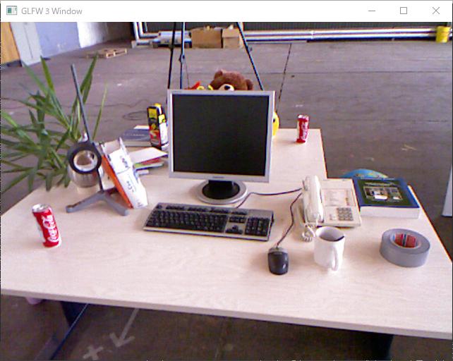
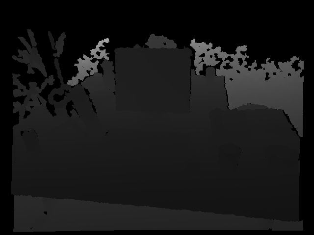
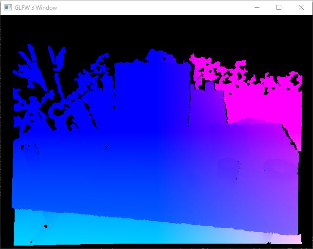
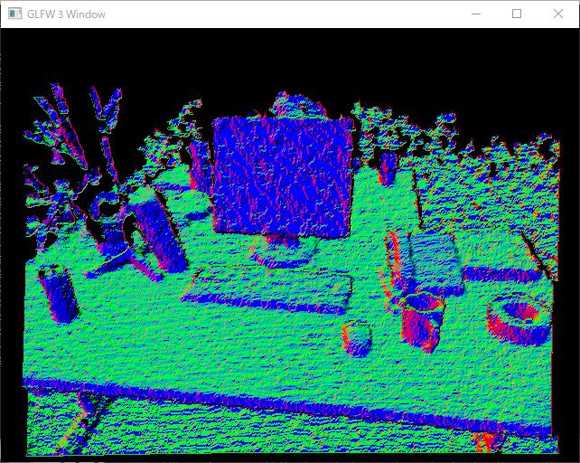
結果
以下に示す,RGB画像,奥行マップ,頂点マップ,法線マップにある通り,目標達成!尚,奥行マップを表示させるようにはしていないので,これは入力画像をそのままここに載せている.
正直なところ,TUM RGB-D Datasetでのカメラ座標系の向き,OpenGLのカメラ座標系との関係が分かっていないので,画像だ出ただけ,と言えばそれだけ.座標軸が想定通りか,今後,検証する必要がある.また,法線マップがガタガタなので,次回はBilateral Filterを実装してみようと思う.