GLSL #11: Bilateral Filter
目標
前回(下記参照)の予告通り,Bilateral Filterを実装する.
実装環境
- Windows 10 64bit
- Visual Studio 2015
- GLEW 3.2.1
- 設定方法はこちらを参照
- GLEW 1.13.0
- 設定方法はこちらを参照
- GLM
- 設定方法はこちらを参照
- DevIL
- 設定方法はこちらを参照
- OpenCV
- 設定方法は外部のWebサイトを参照
- 尚,contribは必要なし
参考サイト
https://www.shadertoy.com/view/4dfGDH
上記,参考サイトはOpenGL ESなので,OpenGL用に一部,処理を変更する必要がある.更に,3チャンネルの画像を想定しているので,1チャンネルの奥行画像を想定した処理に変更する.
main.cpp
- csBilateralFilterクラス Compute Shaderを使って,奥行マップにBilateral Filterをかけるクラス.
- キー操作 「b」キーを押すと,Bilateral Filterがかかった後の法線マップが表示され,それ以外のキーを押すと,元の法線マップが表示される.
#include <glm/glm.hpp>
#include <glm/ext.hpp>
#include <glm/detail/setup.hpp>
#include <opencv2/opencv.hpp>
#include "OpenGLWrapper/window.h"
#include "OpenGLWrapper/shaderUtil.h"
#include "OpenGLWrapper/modelTex.h"
#include "OpenGLWrapper/rgbdTex.h"

// Bilateral filter
// Ref: https://www.shadertoy.com/view/4dfGDH
class csBilateralFilter : public gl::compShader
{
public:
    csBilateralFilter(
        int w,
        int h,
        const string &compShaderName
    ) : gl::compShader(w, h, 1, GL_R32F, GL_RED, GL_FLOAT, compShaderName)
    {
    }

    void csBilateralFilter::execute(
        GLuint inTexID,
        float sigma = 10.0f,
        float bSigma = 0.1f
    )
    {
        glUseProgram(prog);
        {
            GLuint locSigma = glGetUniformLocation(prog, "sigma");
            glUniform1f(locSigma, sigma);
            GLuint locBSigma = glGetUniformLocation(prog, "bSigma");
            glUniform1f(locBSigma, bSigma);

            // Input texture
            glBindImageTexture(0, inTexID, 0, GL_FALSE, 0, GL_READ_ONLY, GL_R32F);
            // Output texture
            glBindImageTexture(1, texID, 0, GL_FALSE, 0, GL_WRITE_ONLY, GL_R32F);
            glDispatchCompute(width / 32, height / 32, depth);
        }
        glUseProgram(0);
    }
};


// Vertex map calculation(前回と同じであるため割愛)
...

// Normal map calculation(前回と同じであるため割愛)
...

class MyWindow : gl::window
{
private:
    csBilateralFilter *myCSBilateralFilter;
    csCalcVertMap *myCSCalcVertMap;
    csCalcNormMap *myCSCalcNormMap;
    gl::rgbdTex *myRGBDTex;
    gl::modelTex *myModelTex;

public:
    MyWindow(
        int w,
        int h,
        const string &wndName,
        const glm::mat3 &K,    // Intrinsic parameters
        const float factor,   // See: http://vision.in.tum.de/data/datasets/rgbd-dataset/file_formats#intrinsic_camera_calibration_of_the_kinect
        const string &colorImgName,
        const string &depthImgName,
        const string &compBilateralFilterShaderName,
        const string &compVertMapShaderName,
        const string &compNormMapShaderName
    ) : window(w, h, wndName)
    {
        // Read images
        cv::Mat imgC = cv::imread(colorImgName);     // Color image
        cv::Mat imgD = cv::imread(depthImgName, -1);    // Depth image
        imgD.convertTo(imgD, CV_32F);
        imgD /= factor;

        // Upload the RGB-D image to your GPU
        myRGBDTex = new gl::rgbdTex(imgC.cols, imgC.rows);
        myRGBDTex->updateRGBDTex(imgC.data, imgD.data);

        // Create computer shaders
        myCSBilateralFilter = new csBilateralFilter(imgC.cols, imgC.rows, compBilateralFilterShaderName);
        myCSCalcVertMap = new csCalcVertMap(imgC.cols, imgC.rows, K, compVertMapShaderName);
        myCSCalcNormMap = new csCalcNormMap(imgC.cols, imgC.rows, compNormMapShaderName);

        // Create a texture polygon to display the results
        myModelTex = new gl::modelTex(imgC.cols, imgC.rows, "../shader/modelTex.vert", "../shader/modelTex.frag");
    }
    ~MyWindow()
    {
        if (myRGBDTex)
        {
            delete myRGBDTex;
            myRGBDTex = NULL;
        }
        if (myCSBilateralFilter)
        {
            delete myCSBilateralFilter;
            myCSBilateralFilter = NULL;
        }
        if (myCSCalcVertMap)
        {
            delete myCSCalcVertMap;
            myCSCalcVertMap = NULL;
        }
        if (myCSCalcNormMap)
        {
            delete myCSCalcNormMap;
            myCSCalcNormMap = NULL;
        }
        if (myModelTex)
        {
            delete myModelTex;
            myModelTex = NULL;
        }
    }

    void render()
    {
        const glm::mat4 rotMat180X = glm::rotate(glm::pi<float>(), glm::vec3(1.0f, 0.0f, 0.0f));
        myModelTex->setModelMat(rotMat180X);

        // Rendering loop
        while (!glfwWindowShouldClose(wnd))
        {
            // Clear color and depth buffers
            glClearColor(0.0f, 0.0f, 0.0f, 0.0f);
            glClear(GL_COLOR_BUFFER_BIT | GL_DEPTH_BUFFER_BIT);


            if (keyID == 'B')
            {
                // Bilateral filter
                myCSBilateralFilter->execute(myRGBDTex->getDepthTexID(), 2.0f, 0.05f);
                // Calculate a vertex map from a depth map
                myCSCalcVertMap->execute(myCSBilateralFilter->getTexID());
            }
            else
            {
                // Calculate a vertex map from a depth map
                myCSCalcVertMap->execute(myRGBDTex->getDepthTexID());
            }
            // Calculate a normal map from a depth map
            myCSCalcNormMap->execute(myCSCalcVertMap->getTexID());

            // Show the results
            myModelTex->render(myCSCalcNormMap->getTexID());

            // Swap front and back buffers
            glfwSwapBuffers(wnd);
            // Poll for and process events
            glfwPollEvents();
        }
    }
};

int main()
{
    glm::mat3 K(525.0f, 0.0f, 0.0f, 0.0f, 525.0f, 0.0f, 319.5f, 239.5f, 1.0f);

    MyWindow wnd(
        640, 480,
        "GLFW 3 Window",
        K, 5000.0f,
        "../data/1311868164.363181.png",
        "../data/1311868164.338541.png",
        "../shader/bilateralFilter.comp",
        "../shader/calcVertMap.comp",
        "../shader/calcNormMap.comp"
    );
    wnd.render();

    return 0;
}
bilateralFilter.comp
現状,カーネルサイズ「mSize」は固定.
// Ref: https://www.shadertoy.com/view/4dfGDH
#version 430

layout (binding = 0, r32f) readonly uniform image2D dataIn;     // Input depth map
layout (binding = 1, r32f) writeonly uniform image2D dataOut;   // Output depth map

uniform float sigma;
uniform float bSigma;
const int mSize = 7;

layout (local_size_x = 32, local_size_y = 32) in;

float normPdf(float x, float sigma)
{
    return 0.39894 * exp(-0.5 * x * x / (sigma * sigma)) / sigma;
}

void main(void)
{
    ivec2 u = ivec2(gl_GlobalInvocationID.xy);
    float c = imageLoad(dataIn, u).r;

    const int kSize = (mSize - 1) / 2;
    float kernel[mSize];
    float finalColor = 0.0;

    // Create the 1-D kernel
    float Z = 0.0;
    for (int i = 0; i <= kSize; ++i)
    {
        kernel[kSize + i] = kernel[kSize - i] = normPdf(float(i), sigma);
    }

    float cc;
    float factor;
    float bZ = 1.0 / normPdf(0.0, bSigma);
    // Read out the texels
    for (int x = -kSize; x <= kSize; ++x)
    {
        for (int y = -kSize; y <= kSize; ++y)
        {
            cc = imageLoad(dataIn, u + ivec2(x, y)).r;
            factor = normPdf(cc - c, bSigma) * bZ * kernel[kSize + y] * kernel[kSize + x];
            Z += factor;
            finalColor += factor * cc;
        }
    }

    imageStore(dataOut, u, vec4(finalColor / Z, 0.0, 0.0, 1.0));
}
結果
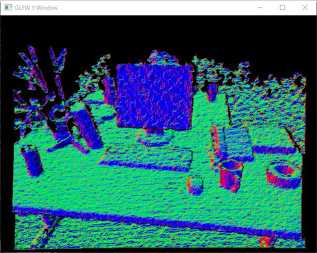
以下に,Bilateral Filterをかける前後の法線マップを示す,尚,かける前の画像は前回の結果である.この通り,目標達成だ!Bilateral Filterをかけた結果は,法線マップの見た目が滑らかになる.
現状,Bilateral Filterのカーネルサイズが固定だが,将来的には可変にしたい.これは,シェーダのmain関数内に固定長の配列が宣言されていることが原因なのだが,何かいい方法はないものだろうか...?